In this blog you will learn about Design of one way slab of first floor of G + 5 building procedure using I.S. 456:2000. Learn Complete Structural Engineering Industry Requirements Practically With Our Daily Blogs Series
Steps:-
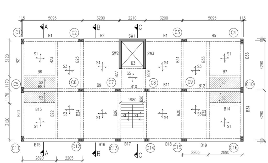
Given:-
1) Grade of Concrete = M20
2) Grade of Steel = Fe500
3) Clear Cover to Reinforcement (c) = 20 mm
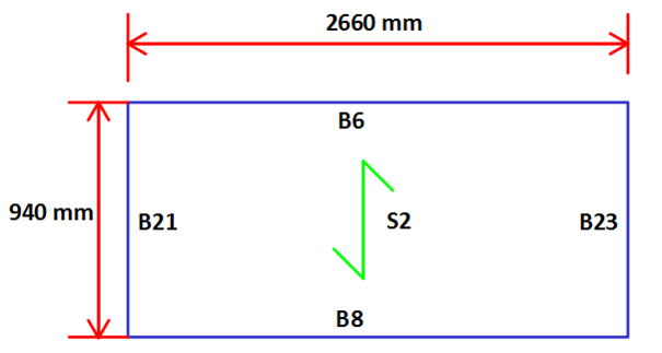
4) Dimension of Slab = (940mm X 2660 mm)
5) Assume Beam Support (Bearing) = 230 mm
6) Unit Weight of Concrete = 25 kN/m2
Step 1 :-Aspect Ratio
(Refer Cl. No. D-1.11, Page No. 90 , I.S. 456:2000)
Lx = 940 mm & Ly = 2660 mm …(Given)
Therefore, Ly/Lx = 2660/940 = 2.82 > 2 …(One Way Slab)

Step 2 :-Trial Depth of Slab (D)
Basic Value (B.V.) = L / D = 20
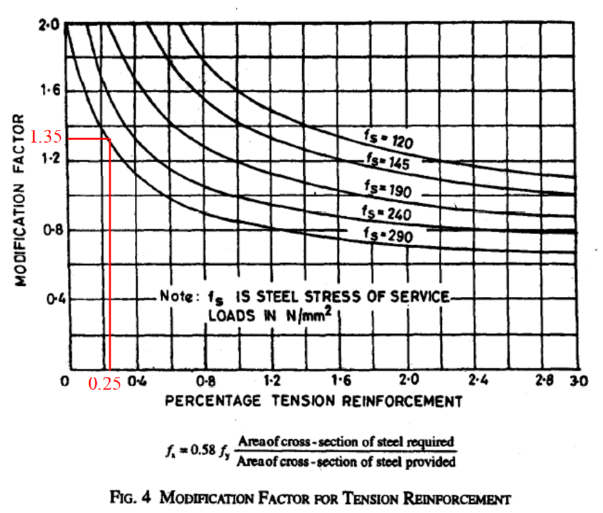
Assume % of Steel = 0.25 %
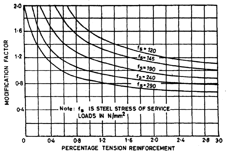
Therefore, Modification Factor (M.F.) = 1.35 …(Refer Fig. 4 , Page No. 38 I.S.456:2000)
Therefore, Effective Depth (d) = SPAN/B.V.X.N.F. = [940/ (20 X 1.35)] = 34.81 mm
Assume Bars to be Provided of Diameter = 8 mm & Provide Clear Cover to Reinforcement = 20 mm
Therefore, Overall Depth of Slab (D) = d + c + (8/2) = 34.81 + 20 + 4 = 58.81 mm
Assume , Overall Depth of Slab (D) = 125 mm
Therefore, Effective Depth Provided (dprovided) = D – c – (8/2) = 125 – 20 – 4 = 101 mm
Step 3 :-Effective Span (le)
Minimum of, i) Le = Lx + Bearing = 940 + 230 = 1170 mm
ii) Le = Lx + d = 940 + 101 = 1041 mm
Therefore, Effective Span (Le) = 1041 mm
Step 4 :- Load Calculations
Consider 1 m Strip of Slab,
i) Self Weight of Slab (DL) = D X Unit Weight of Concrete
= 0.125 X 25
= 3.125 kN/m2
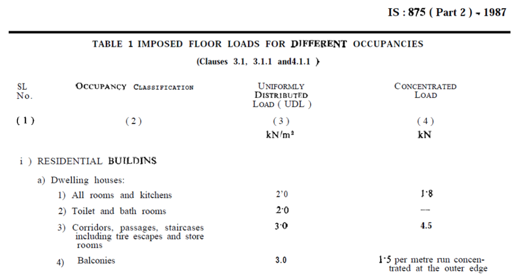
ii) Live Load (LL) = 2 kN/m2 …[Refer Table No. 1 , Page No. 7, I.S. 875 (Part 2) : 1987]
iii) Super Imposed Dead Load (SIDL) =
Floor Finish = Wt. of Screeding (50 mm Thk.) + Flooring (10 mm Thk.) + Sunk Load(325 mm Thk.)
= (0.05 X 24) + (0.01 X 22) + (0.325 X 20)…[Refer I.S. 875 (Part 1) :1987]
= 7.92 kN/m2
≈ 8 kN/m2
Total Load (W) = 3.125 + 2 + 8
= 13.125 kN/m2
Total Ultimate Load (Wu) = 13.125X 1.5 ≈ 19.7 kN/m2
Step 5 :- Maximum Design Bending Moment (Mumax)
Refer Table No. 26, Page No. 90 , I.S. 456:2000
Span Moment :-
Mumax= Wu . le2 / 8
Mumax = 19.7 X 1.0412 / 8
Mumax = 2.668 kN.m
Therefore ,Mumax= 2.668 kN.m
Step 6 :- Check For Depth
Equate Mumax & Mulim,
Mumax = Mulim
2.668 X 106 = 0.133 X fck X b X dreq2
2.668 X 106 = 0.133 X 20 X 1000 X dreq2
dreq= 31.67 mm < 101mm …(dreq< dprovided)
Therefore, Safe
Step 7 :- Area of Steel Calculation :-

Spacing of Bars :-
As per Cl. No. 26.3.3 (b) , Page No. 46 , I.S. 456 : 2000
Maximum Spacing
Between Bars < Minimum of i) 3d
ii) 300 mm
Therefore,
Maximum Spacing Between Bars = i) 3 X 101 = 303 mm
ii) 300 mm
Note:- Generally We Provide 200 mm Maximum Spacing Between Bars.

= 61.7 mm2
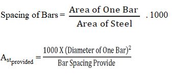
Spacing of Bars = (Area of One Bar / Area of Steel) . 1000
Consider Bars to Provide are of Diameter 8mm.
Therefore, Spacing of Bars = [(π/4) X 82 / 61.7] X 1000 = 814.78 mm
Note:- Generally We Provide 200 mm Maximum Spacing Between Bars.

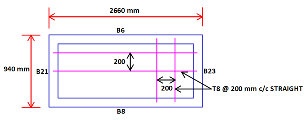
Therefore, Provide 8 mm Diameter Bars at 200 mm c/c.
Step 8 :- Distribution Steel Calculation :-
Dst = 0.12 % of the Gross Area of Slab …(For Fe500)
Therefore, Dst= (0.12/100) X Ag
Dst= (0.12/100) . b . D …(Where, b = 1000 mm &
D = Overall Depth of Slab)
Dst= (0.12/100) X 1000 X 125
= 150 mm2
Spacing of Bars = (Area of One Bar / Area of Steel) . 1000
Consider Bars to be Provide are of Diameter 8 mm.
Therefore, Spacing of Bars = [(π/4) X 82 / 150] X 1000 = 335.15 mm
Maximum Spacing
Between Bars < Minimum of i) 5d = 5 X 101 = 505 mm
ii) 450 mm
Note:- Generally We Provide 200 mm Maximum Spacing Between Bars.

Therefore, Provide 8 mm Diameter Bars at 200 mm c/c.
Step 9 :- Check For Deflection :-
% of Steel = Pt = 100. Astreq / b.d
Therefore, Pt = (100 X 61.7) / (1000 X 101) = 0.061 %

Therefore, Fs = 0.58 X 500 X (61.7 / 251.36) = 71.18 N/mm2
% of Steel Provided = Pt = 100. Astprovided / b.d
Therefore , Pt = (100 X 251.36) / (1000 X 101) = 0.248 %
M.F. = 2.0

As, dreq < dprovided …Safe for Deflection.
REINFORCEMENT DETAILS :-


Nice effort!!
Well described
Nice Blog