In this blog you will learn Manual Design Of Footing of G+5 Building Using I.S. 456:2000 with the help of example.
Step by step guid to clear concept
Learn Complete Structural Engineering Indusry Requirements Practically With Our Daily Blogs Series
Steps:
Given:
- Grade of Concrete = M20
- Grade of Steel = Fe500
- Clear Cover to Reinforcement (c) = 50 mm
- Column Dimension = 300 X 600 mm
- Net Soil Bearing Capacity (S.B.C.) = 300 kN/m2
- Assume Axial Load (P) from Column to Footing = 1500 kN
Load Calculation (Step 1):
Load From Column = 1500 kN
Self Weight of Footing = Assume 10% of the column load
= (10/100) X 1500
= 150 kN
———————————————————–
Total Weight (W) = 1650 kN
Area of Footing (A) (Step 2):
Area of Footing (A) = Total Weight (W) / Net Soil Bearing Capcity (S.B.C.)
= 1650 / 300
= 5.5 m2
Take Equal Projections From Both Sides,
5.5 = (0.6 + 2x) . (0.3 + 2x)
5.5 = 0.18 +1.2x + 0.6x + 4×2
5.5 = 0.18 +1.8x + 4×2
Therefore, by Solving Above Equation,
x = 0.95 m
Take Projection of 1 m on Both Side.
Therfore, Size of Footing = (0.3+ 2 X 1 ) & (0.6 + 2 X 1) = 2.3 X 2.6 m
Therefore Area of Footing Provided = 2.3 X 2.6 = 5.98 m2

Upward Soil Pressure (Pau) (Step 3):
Pau = (Factored Load of Column / Actual Area of Footing Provided)
= 1.5 X 1500 / 5.98
Pau= 376.25 kN/m2
Bending Moment (B.M.) (Step 4):
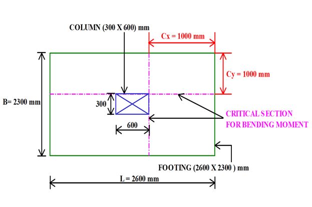
The Critical Section for B.M. Along the Column Face as Shown in the Figure 2,
From X-axis:

= (2.6 – 0.6) / 2
= 1 m
Consider a Strip of 1m.
Therefore, Mux = [Pau X 1 X (Cx2/2)]
= [376.25 X 1 X (12 /2)]
Mux = 188.125 kN.m

From Y-axis:

= (2.3 – 0.3) / 2
= 1 m
Therefore, Muy = [Pau X 1 X (Cy2/2)]
= [376.25 X 1 X (12 /2)]
Muy = 188.125 kN.m
Depth of Footing Required (dreq) (Step 5):
Equate The Maximum Bending Moment (Max. of Mux & Muy) With Limiting Moment of Resistance ,
Consider a Strip of 1m.
Mumax= Mulim
188.125 X 106 = 0.133 fck.b.dreq2
188.125 X 106 = 0.133 X 20 X 1000 X dreq2
dreq = 265.94 mm
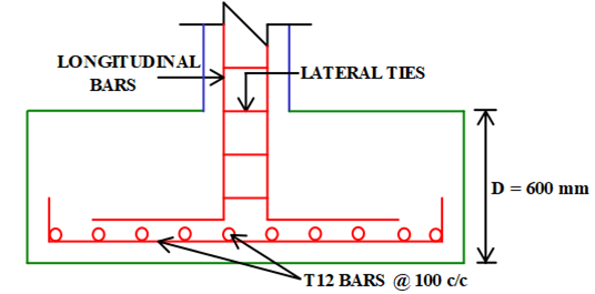
Provide 12 mm Diameter Bars at a Clear Cover of 50 mm.
Therefore, Overall Depth (D) = 265.94 + 50 + (12/2)
= 321.94 mm ≈ 600 mm …(rounded -off on higher side)
Overall Depth (D) = 450 mm
Therefore, Effective Depth Provided (dprovided) = 600 – 50 – (12/2) = 544 mm
Area of Steel Calculation (Ast) (Step 6):
Astx Along X-Direction:

Astx = 826.8 mm2
Provide 12 mm Diameter Bars.
Spacing = (π/4 × 12² ÷ 826.8) ×100
= 136.8 mm ≈ 125 mm
Provide 12 mm Diameter Bars @ 125 mm c/c
Asty Along Y-Direction:

Asty = 826.8 mm2
Provide 12 mm Diameter Bars.
Spacing = (π/4 × 12² ÷ 826.8) ×100
= 136.8 mm ≈ 100 mm
Provide 12 mm Diameter Bars @ 100 mm c/c
Check For One Way Shear (Step 7):
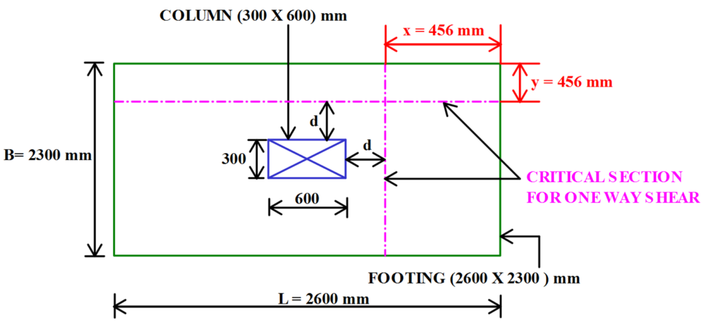
The Critical Section for One Way Shear is Taken at a Distance of ‘d’ From Column Periphery.
The Offset x = Cx – d = 1 – 0.544 = 0.456 m
Similarly, y = Cy – d = 1 – 0.544 = 0.456 m
Depth of Footing at Critical Section (d’) = 544 mm
Shear Force Along X-Direction :-
Vux = x . L . Pau = 0.456 X 1 X 376.25 = 171.57 kN
Shear Force Along Y-Direction :-
Vuy = y . B . Pau = 0.456 X 1 X 376.25 = 171.57 kN
Vumax = 209.2 kN
Nominal Shear Stress (τv):
τv = Vumax/ b’.d’ = [(171.57 X 10³) / (1000 X 544)] = 0.32 N/mm2

% of Steel (Pt):
Pt = 100 Astmax / b’d’ = [(100 X 1130) / (1000 X 544)] = 0.21 %
Design Shear Stress (τc):
τc = 0.32 N/mm2 > 0.32 N/mm2
As, τc > τv … Safe in One Way Shear
| Pt | τc ( For M20) |
| <0.15 | 0.28 |
| 0.21 | ? |
| 0.25 | 0.36 |
Check For Two Way Shear (Step 8):
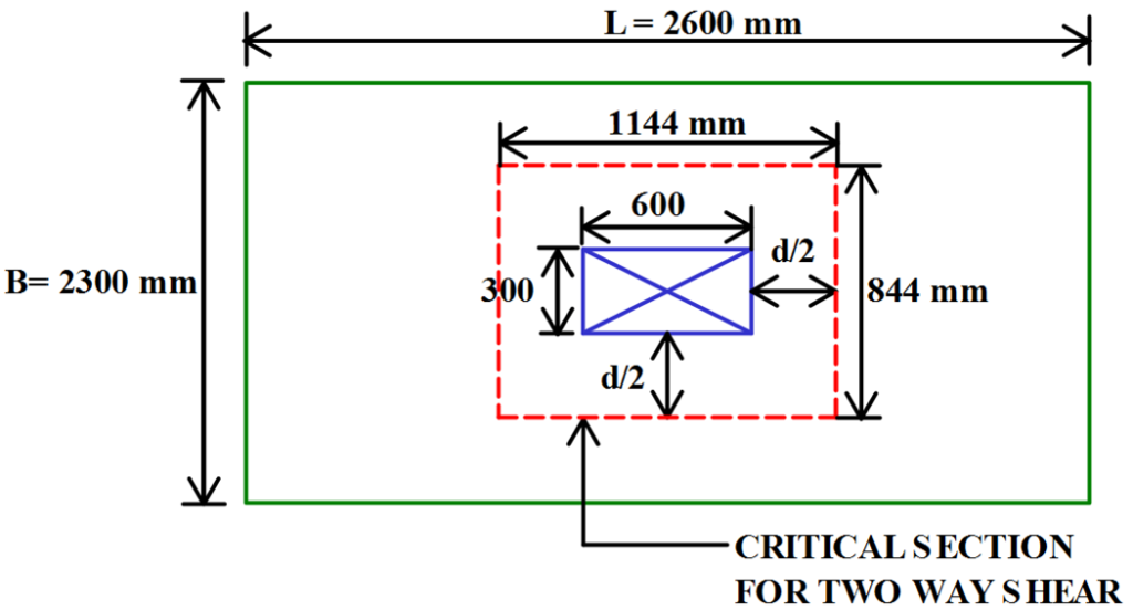
The Critical Section for Two Way Shear is Taken at a Distance of ‘d/2’ From Column Periphery.
Depth of Footing at Critical Section (D’) = 750 mm
Effective Depth at Critical Section = d’ = 600 – 50 – (12/2 ) = 544 mm
b’ = 2 . Perimeter of Critical Section
= 2 X (1144 + 844)
= 3976 mm

Shear Force on Shaded Area is Given by,
Vu = (Footing Area – Critical Section Area) . Upward Soil Pressure
Vu = [(2.6 X 2.3) – (1.144 X 0.844)] X 376.25
Vu = 1886.7 kN
Nominal Shear Stress (τv):
τv = Vumax/ b’. d’ = [(1886.7 X 103) / (3976 X 544)] = 0.87 N/mm2
Design Shear Stress (τc’):
τc‘= ks. (0.25√fck )
Where, ks= Minimum of, i) 1
ii) 0.5 + βc = 0.5 + 0.5 = 1
Where, βc = (Breadth / Depth)column = 300 / 600 = 0.5
Therefore, ks= 1
Therefore, τc‘= 1 X (0.25√20) = 1.118 N/mm2 > 0.87 N/mm2
As, τc > τv … Safe in Two Way Shear


Nice 👍 sir
First time someone explain all the thing that I want to know…
Thanks a lot sir.. 👍
Nice information
Very nice