In this blog, you will learn step by step about the design of doubly reinforced beam of first floor of G+5 building procedure using I.S. 456:2000. For daily blogs, subscribe to our blog page and learn complete information about the structural engineering industry
Steps:-

Given:-
1) Grade of Concrete = M20
2) Grade of Steel = Fe500
3) Clear Cover to Reinforcement (c) = 25 mm
4) Length of Beam :- B24 & B25 = 4060 mm
5) Unit Weight of Concrete = 25 kN/m2
6) Slab Dimensions :- S3 = (1975 mm X 4060 mm) & S4 = (3050 mm X 4060 mm)
7) Floor to Floor Height (H) = 3000 mm

Step 1 :- Trial Dimension of The Beam :-
Assume the Width of The Beam (b) = 230 mm
Effective Depth of Beam (d) = (L/10) to (L/15) = (4290/10) to (4290/15)
= 429 mm to 286 mm
Take, d = 325 mm
Assume, 20 mm Diameter Bars are to be Provided at a Clear Cover of 25 mm.
Therefore, Overall Depth (D) = 325 + (20/2) + 25 = 360 mm ≈ 375 mm
…(Rounded off on Higher Side)
Therefore, Effective Depth of Beam Provided (d) = 375 – (20/2) – 25 = 340 mm
Step 2 :- Effective Span (Le) :-
Minimum of The Following ,
i) Le = L + d = 4060 + 340 = 4400 mm
ii) Le = L + Bearing = 4060 + 230 = 4290 mm
Therefore, Effective Span (Le) = 4290 mm
Step 3 :- Load Calculations :-
Load on Beam B24 & B25 :-
i) Super Imposed Dead Load (SIDL) :-
Wall Load = Wall Thickness X Floor to Floor Height X Unit Weight of Bricks
= (0.150 X 3 X 20) = 9 kN/m
…(No Deduction of Depth of Beam is Made From Floor to Floor Height)
ii) Slab Load Transferring on Beam :-
Slab S3 :-
a) Self Weight of Slab (DL) = D X Unit Weight of Concrete
= 0.125 X 25
= 3.125 kN/m2
b) Live Load (LL) = 2 kN/m2 …[Refer Table No. 1 , Page No. 7 , I.S. 875 (Part 2) : 1987]
c) Super Imposed Dead Load (SIDL) =
Floor Finish = Wt. of Screeding (50 mm Thk.) + Flooring (10 mm Thk.)
= (0.05 X 24) + (0.01 X 22) …[Refer I.S. 875 (Part 1) : 1987]
= 1.42 kN/m2
≈ 1.5 kN/m2
Total Load of Slab S3 (w) = 3.125 + 2 + 1.5 = 6.625 kN/m2
Trapezoidal Load of Slab S3 is Transferring on Beam B24 & B25 Because S3 Slab is Two Way Slab Which is Given by,
WS3 = [{(w. Lx)/2} X {1- (1/ 3. β2)}] Where, β = l_y/l_x
= {(6.625 X 1.975 ) / 2} X [1- {1/ 3 X (4.06/1.975)2}]
= 6.02 kN/m
Slab S4 :-
a) Self Weight of Slab (DL) = D X Unit Weight of Concrete
= 0.125 X 25
= 3.125 kN/m2
b) Live Load (LL) = 2 kN/m2 …[Refer Table No. 1, Page No. 7, I.S. 875 (Part 2) : 1987]
c) Super Imposed Dead Load (SIDL) =
Floor Finish = Wt. of Screeding (50 mm Thk.) + Flooring (10 mm Thk.)
= (0.05 X 24) + (0.01 X 22) … (Refer I.S. 875 (Part 1) : 1987)
= 1.42kN/m2
≈ 1.5 kN/m2
Total Load of Slab S4 (w) = 3.125 + 2 + 1.5 = 6.625 kN/m2
Trapezoidal Load of Slab S4 is Transferring on Beam B24 & B25 Which is Given by,
WS4 = [{(w. Lx)/2} X {1- (1/ 3. β2)}]
={(6.625 X 3.05) / 2} X [1- {1/ 3 X (4.06/3.05)2}]
= 8.2 kN/m
Therefore, Total Load of Slabs Transfers on Beam B24 & B25 = WS1 + WS4
= 6.02 + 8.2
= 14.22 kN/m
iii) Self Weight of Beam (DL) = b X D X Unit Weight of Concrete
= 0.230 X 0.375 X 25
= 2.156 kN/m
Total Load on Each Beam B24 & B25 (W) = 9 + 14.22 + 2.156 = 25.376 kN/m
≈ 25.4 kN/m
Ultimate Load (Wu) = 25.4 X 1.5 = 38.1 kN/m
Step 4 :- Bending Moment (Mu) :-
Max. Moment on Continuous
Beam (B24 & B25) is (M) = W . Le2 / 8
= (25.4 X 4.292) / 8
= 58.43 kN.m
Ultimate Moment on Continuous
Beam (B20 & B21) is (Mu) =58.43X 1.5 = 87.65 kN.m
CONTINUOUS BEAM HAVING TWO EQUAL SPAN CARRYING UNIFORMALLY DISTRIBUTED LOAD (UDL) OVER ENTIRE SPAN :-


Step 5 :- Limiting Moment of Resistance :-
Mulim= 0.133 fck.b.d2
Mulim= 0.133 X 20 X 230 X 3402
Mulim= 0.133 X 20 X 230 X 3402
Mulim= 70724080 N
Mulim= 70724080 / 106
Mulim= 70.72 kN.m
As, Mulim< Mu
Note :- Either We Have to Increase Depth and Design as a Singly Reinforced Beam or if We Are Not Allowed to Increase Depth of Beam Then We Will Design the Beam as a Doubly Reinforced Beam. So We Design Assumed Beam of 230 X 375 mm As Doubly Reinforced Beam.
Step 6 :- Balanced Moment (Mu2) :-
Equate, Mu2 = Mu – Mulim
Mu2 = 87.65 – 70.72
Mu2 = 16.93 kN.m
Step 7 :- Area of Steel Calculation (Ast) :-
[Refer Cl. No. 26.5.1.1 (a) & (b), Page No. 46 & 47,I.S. 456 : 2000]

Astmin = As/bd = 0.85/ Fy
Astmin= As = [(0.85 X 230 X 340) / 500]
Astmin= As = 132.94 mm2
Astmax = 0.04 b.D
= 0.04 X 230 X375
= 3450 mm2
i) Steel in Tensile Zone :-
Astreq= Ast1+Ast2


[For kumax & fsc Refer above Tables From, Illustrated Design of Reinforced Concrete Buildings by S. R. Karve & V. L. Shah]
ii) Steel in Compression Zone :-
dc / d= (D – d) / d = (375 – 340) / 340 = 0.1
By Interpolation,
fsc = 412 N/mm2 …Refer Table 4.2.2

Step 8 :- Check For Shear :-
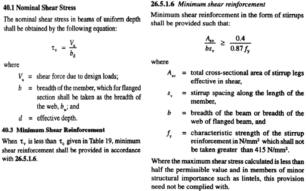
Codal Provisions for Shear :- [Refer Cl. No. 26.5.1.6, Page No. 48 & Cl. No. 40.1, 40.3, Page No. 72 of I.S. 456 : 2000]


i) Maximum Shear Force (Vu) :-
V = (5.W . Le/ 8)
= [(5 X 25.4 X 4.29) / 8]
= 68.1 kN
Vu= 68.1 X 1.5 = 102.15 kN
ii) Nominal Shear Stress (τv) :-
τv = Vu / b.d
= [(102.15 X 10³) / (230 X 340)]
= 1.3 N/mm2 < 2.8 N/mm2 (τcmax) (Refer Table 20, I.S. 456:2000)
iii) % of Steel (Pt) :-
Pt= [(100. Astprovided) / b.d]
Therefore , Pt = (100 X 942.6) / (230 X 340) = 1.2 %
iv) Design Shear Stress (τc) :- (Refer Table No. 19, Page No.73, I.S. 456 : 2000)
By Interpolation,
τc = [0.62 + {(0.67- 0.62) / (1.25 – 1)}X (1.2 – 1)]
= 0.66 N/mm2 < 1.29 N/mm2
As, τc < τv
We Need to Design For Shear Reinforcement.

As per Table No. 20 , Page No. 73 , I.S. 456 : 2000
Maximum Shear Stress for M20 Grade Concrete is, τcmax= 2.8 N/mm2
Therefore, Beam B20 & B21 Both Are Safe in Shear.
Step 9 :- Design of Shear Reinforcement :-
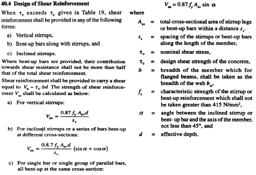
(Refer Cl. No. 40.1, Page No. 73 of I.S. 456 : 2000]
i) Shear Resisted by Stirrups (Vus) :-
Vus= Vu – Vuc ….( For Simply Supported Beam )
= Vu – τc .b.d
= 102.15 X 10³ – 0.66 X 230 X 340
= 50538 N
= 50.538 kN
Provide 2-Legged 8mm Diameter Stirrups

iii) Check For Stirrups Spacing :-
Spacing of Stirrups Should Not be Greater Than Minimum of The Following,
Spacing of Stirrups (Sv) = Min. of i) 0.75d
ii) 300 mm
Therefore, Spacing of Stirrups (Sv) = i) 0.75 X 390 = 292.5 mm < 294.24 mm Or
ii) 300 mm > 294.24 mm
Therefore, Spacing of Stirrups (Sv) = 292.5 mm ≈ 250 mm
Therefore, Provide 2-Legged 8 mm Diameter Stirrups at a Spacing of 250 mm c/c.
Step 10 :- Check For Deflection :-
Permissible Deflection (Δ) = Le / 350 = 4290 / 350 = 12.25 mm
For Simply Supported Beam,


Civil engineering
The formula is so helpful