In this blog, you will learn step by step about the design of singly reinforced beam of first floor of G+5 building procedure using I.S. 456:2000. For daily blogs, subscribe to our blog page and learn complete information about the structural engineering industry
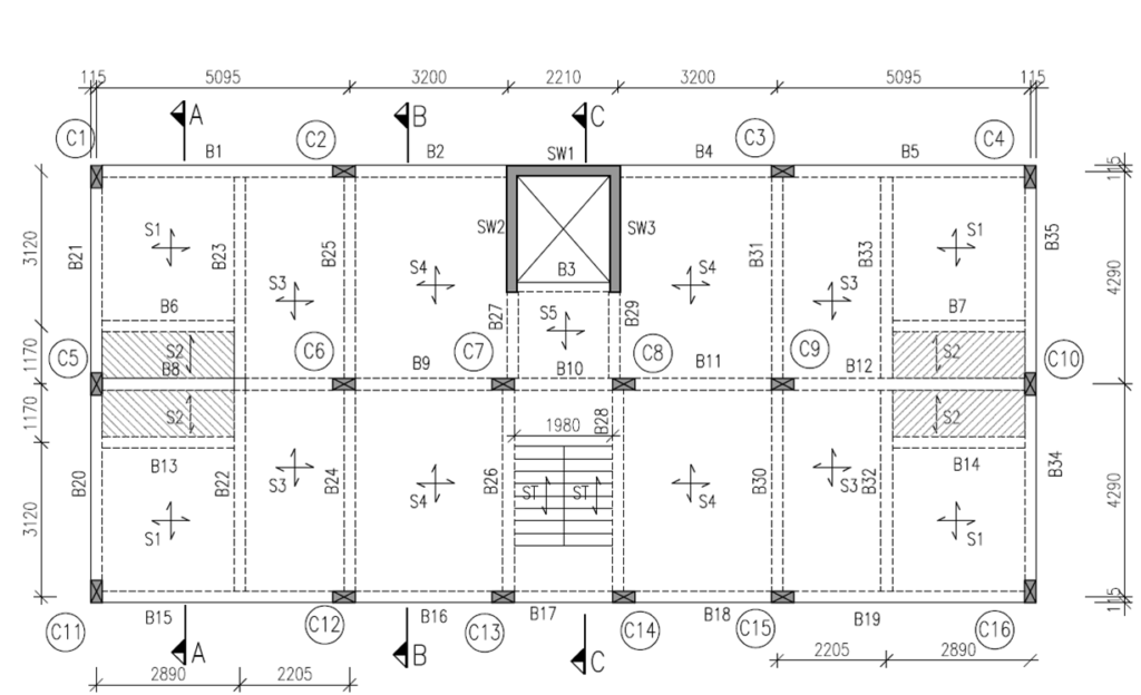
Steps :-
Given :- (SINGLY REINFORCED BEAM)
1) Grade of Concrete = M20
2) Grade of Steel = Fe500
3) Clear Cover to Reinforcement (c) = 25 mm
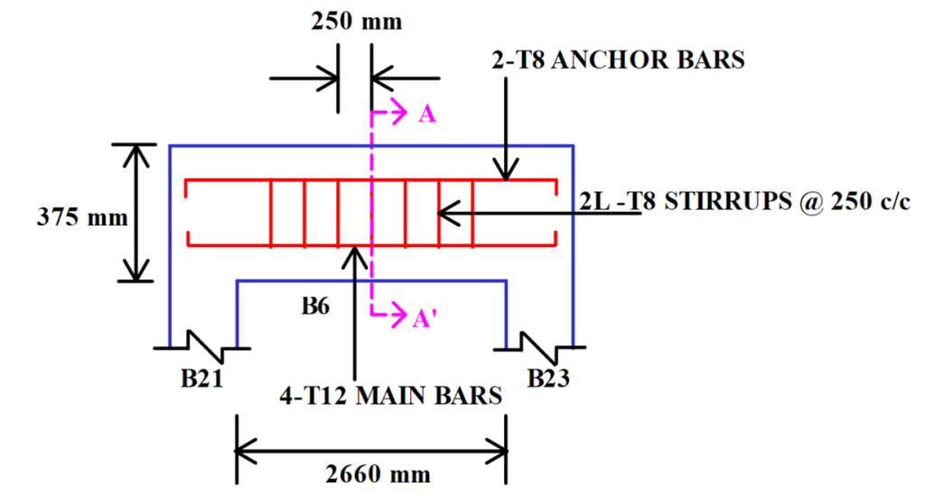
4) Length of Beam = 2660 mm
5) Unit Weight of Concrete = 25 kN/m2
6) Slab Dimensions :- S1 = (2660 mm X 2890 mm) & S2 = (940 mm X 2660 mm)
7) Floor to Floor Height (H) = 3000 mm
Step 1 :- Trial Dimension of The Beam :-
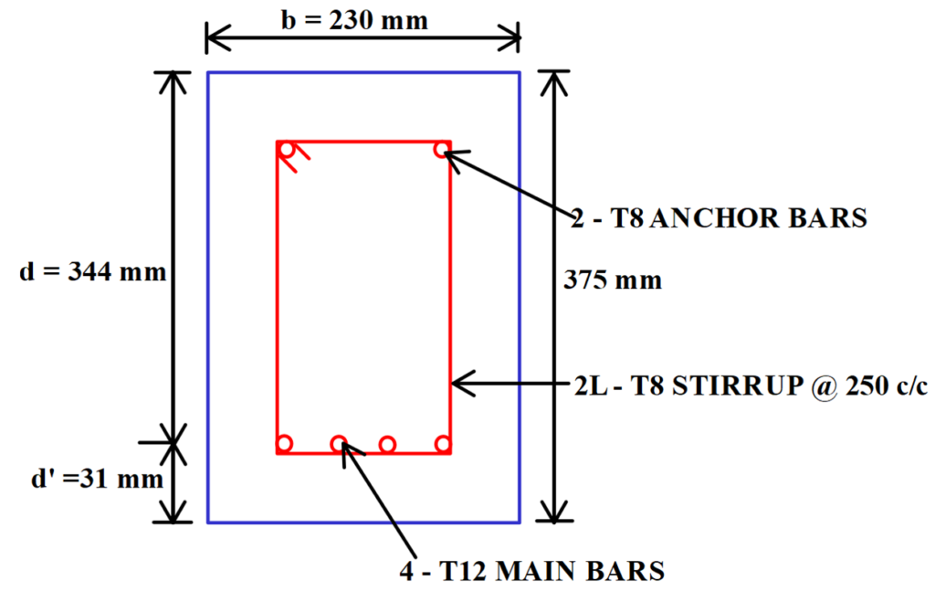
Assume the Width of The Beam (b) = 230 mm
Effective Depth of Beam (d) = (L/10) to (L/15) = (2660/10) to (2660/15)
= 266 mm to 177.33 mm
Take, d = 300 mm …(Rounded off on Higher Side)
Assume, 12 mm Diameter Bars are to be Provided at a Clear Cover of 25 mm.
Therefore, D = 300 + (12/2) + 25 = 331 mm ≈ 375 mm …(Rounded off on Higher Side)
Therefore, Effective Depth of Beam Provided (d) = 375 – (12/2) – 25 = 344 mm
Step 2 :- Effective Span (Le) :-
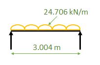
Le = L + d = 2660 + 344 = 3004 mm
Step 3 :- Load Calculations :-
i) Super Imposed Dead Load (SIDL) :-
Wall Load = Wall Thickness X Floor to Floor Height X Unit Weight of Bricks
= (0.150 X 3 X 20) = 9 kN/m
…(No Deduction of Depth of Beam is Made From Floor to Floor Height)
ii) Slab Load Transferring on Beam :-
Slab S2 :-
a) Self Weight of Slab (DL) = D X Unit Weight of Concrete
= 0.125 X 25
= 3.125 kN/m2
b) Live Load (LL) = 2 kN/m2 …[Refer Table No. 1 , Page No. 7 , I.S. 875 (Part 2) : 1987]
c) Super Imposed Dead Load (SIDL) =
Floor Finish = Wt. of Screeding (50 mm Thk.) + Flooring (10 mm Thk.)
+ Sunk Load(325mm Thk.)
= (0.05 X 24) + (0.01 X 22) + (0.325 X 20)…[Refer I.S. 875 (Part 1) :1987]
= 7.92 kN/m2
≈ 8 kN/m2
Total Load of Slab S2 (w) = 3.125 + 2 + 8 = 13.125 kN/m2
Rectangular Load of Slab S2 is Transferring on Beam B6 Because S2 Slab is One Way Slab Which is Given by,
WS2 = [(w. Lx) / 2] = [(13.125 X 1.17) / 2] = 7.678 kN/m
Slab S1 :-
a) Self Weight of Slab (DL) = D X Unit Weight of Concrete
= 0.125 X 25
= 3.125 kN/m2
b) Live Load (LL) = 2 kN/m2 …[Refer Table No. 1 , Page No. 7 , I.S. 875 (Part 2) : 1987]
c) Super Imposed Dead Load (SIDL) =
Floor Finish = Wt. of Screeding (50 mm Thk.) + Flooring (10 mm Thk.)
= (0.05 X 24) + (0.01 X 22) …[Refer I.S. 875 (Part 1) : 1987]
= 1.42kN/m2
≈ 1.5 kN/m2
Total Load of Slab S1 (w) = 3.125 + 2 + 1.5 = 6.625 kN/m2
Triangular Load of Slab S1 is Transferring on Beam B6 Because S1 Slab is Two Way Slab Which is Given by,
WS1 = [(w. Lx)/3] = [(6.625 X 2.66)/3) = 5.874 kN/m
Therefore, Total Load of Slabs Transfering on Beam B6 = WS1 + WS2 = 5.874+7.678
= 13.55 kN/m
iii) Self Weight of Beam (DL) = b X D X Unit Weight of Concrete
= 0.230 X 0.375 X 25
= 2.156 kN/m
Total Load on Beam B6 = Wall Load + Slab load + Self Wt. of Beam
= 9 + 13.55 + 2.156 = 24.706 kN/m
Ultimate Load (Wu) = 24.706 X 1.5 = 37.059 kN/m.
Step 4 :- Bending Moment (Mu) :-
Mu= Wu . Le2/ 8 = 37.059 X 3.0042 / 8 = 41.8 kN.m
Step 5 :- Check For Depth :-
Equate Mumax & Mulim,
Mumax = Mulim
41.8 X 106 = 0.133 X fck X b X dreq2
41.8 X 106 = 0.133 X 20 X 230 X dreq2
dreq= 261.38 mm < 344mm …(dreq< dprovided)
Therefore, Safe
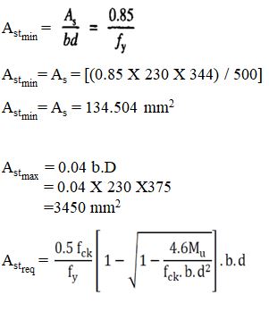
Step 6 :- Area of Steel Calculations (Ast) :-
[Refer Cl. No. 26.5.1.1 (a) & (b),Page No. 46 & 47,I.S. 456 : 2000]
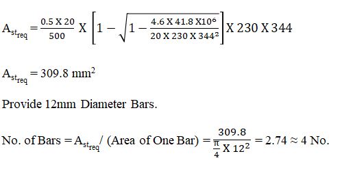
Therefore, Provide 4-T12 Bars.
Therefore, Astprovided = (One Bar Area). (No. of Bars to be Provided)
= π/4 X〖 12〗^2 X 4
Astprovided = 452.45 mm2
>Astmin (134.504 mm2) …ok
>Astmax (3450 mm2) …ok
Step 7 :- Check For Shear :-
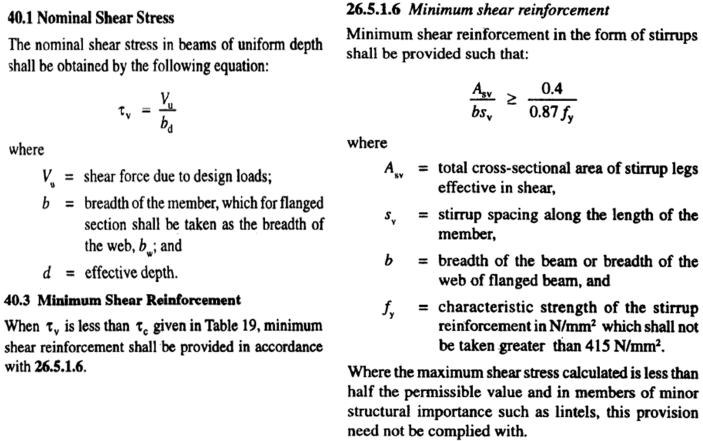
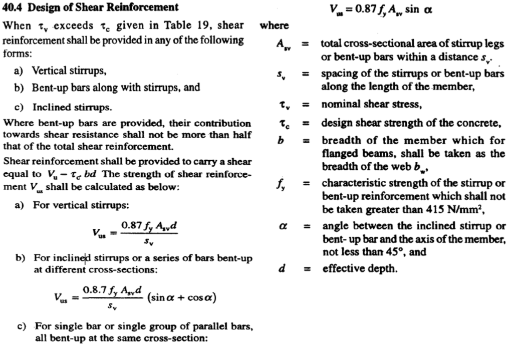
Codal Provisions for Shear :- [Refer Cl. No. 26.5.1.6, Page No. 48 & Cl. No. 40.1, 40.3, Page No. 72 of I.S. 456 : 2000]
i) Maximum Shear Force (Vu) :-
Vu= Wu . Le/ 2 ….( For Simply Supported Beam )
= [(37.059 X 3.004) / 2]
= 55.662 kN
ii) Nominal Shear Stress (τv) :-
τv = Vu / b.d
= [(55.662 X 10³) / (230 X 344)]
= 0.7 N/mm2
iii) % of Steel (Pt) :-
Pt= [(100. Astprovided) / b.d]
Therefore , Pt = (100 X 452.45) / (230 X 344) = 0.57 %
iv) Design Shear Stress (τc) :- (Refer Table No. 19, Page No.73, I.S. 456 : 2000)
By Interpolation,
τc = [0.48 + {(0.56-0.48) / (0.75-0.5)}X (0.57-0.5)]
= 0.5 N/mm2 < 0.7 N/mm2
As, τc < τv
We Need to Design For Shear Reinforcement.
| Pt | τc (For M20) |
| 0.5 | 0.48 |
| 0.57 | ? |
| 0.75 | 0.56 |
As per Table No. 20 , Page No. 73 , I.S. 456 : 2000
Maximum Shear Stress for M20 Grade Concrete is, τcmax= 2.8 N/mm2
Therefore, Beam B6 is Safe in Shear.
Step 8 :- Design of Shear Reinforcement :-
i) Shear Resisted by Stirrups (Vus) :-
Vus= Vu – Vuc ….( For Simply Supported Beam )
= Vu – τc .b.d
= 55.662 X 10³ – 0.5 X 230 X 344
= 16102 N
= 16.102 kN
Provide 2-Legged 8mm Diameter Stirrups
Asv = 2 X π/4 X 64 = 100.544 mm2
ii) Spacing of Stirrups (Sv) :-

iii) Check For Stirrups Spacing :-
Spacing of Stirrups Should Not be Greater Than Minimum of The Following,
Spacing of Stirrups (Sv) = Min. of i) 0.75d
ii) 300 mm
Therefore, Spacing of Stirrups (Sv) = i) 0.75 X 344 = 258 mm
Or
ii) 300 mm
Therefore, Spacing of Stirrups (Sv) = 258 mm ≈ 250 mm
Therefore, Provide 2-Legged 8 mm Diameter Stirrups at a Spacing of 250 mm c/c.
Step 9 :- Check For Deflection :-
Permissible Deflection (Δ) = Le / 350 = 3004 / 350 = 8.58mm
For Simply Supported Beam B6,

NOTE :- Deflection Should be Checked for Working Loads.
As, δmax < Δ …Safe for Deflection

Very informative